TM 5-3895-383-24
Component Locations
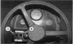
Illustration 39
Front Operator Control Console
(1) Propel range switch. (4) Throttle switch.
Propel range switch (1) and throttle switch (4) are located at
the front operator control console.
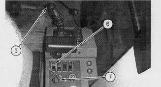
Illustration 40
Right Operator Control Console
(5) Vibratory on/off control switch. (6) Switch for the vibratory
amplitude control. (7) Control for the variable frequency.
Vibratory on/off control switch (5) is located on top of the
propel control lever. The vibration control switch turns the
vibratory system on and off. The switch for the vibratory
amplitude control (6) is located at the right operator control
console. The switch for the vibratory amplitude control is used
to select the vibratory amplitude (HIGH or LOW).
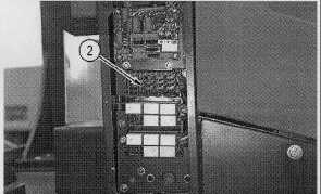
Illustration 41
Location Of The Vibratory Fuse
(2) Fuse.
Fuse (2) is located on the fuse panel on the front of the
operator console. The rating of the fuse is 10 amperes.
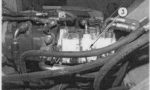
Illustration 42
Location for the Vibratory Control Solenoids
(3) Vibratory control solenoids.
Solenoids (3) are located on the vibratory pump. The two-
position solenoids control the swashplate of the vibratory
pump.
11-38