TM 5-3895-382-24
Gear Group (Front) - Install
SMCS Code: 1206-012
Installation Procedure
NOTICE
Keep all parts clean from contaminants.
Contaminants may cause rapid wear and shortened
component life.
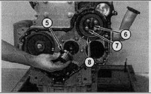
Illustration 139
1.
Install fuel injection pump gear (8) on the engine.
2.
Install four bolts (7) on fuel injection pump gear (8).
3.
Install nut (6) and the spring washer on fuel injection
pump gear (8). Tighten the nut to a torque of 44 Nm
(32 lb-ft).
4.
Install idler gear hub (5) on the engine.
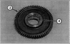
Illustration 140
5.
Use a suitable press to Install new bushings (4) into
idler gear (2).
6.
Machine the bores for clearance on idler gear hub (5).
The bore should have a clearance of 0.07 ±0.03 mm
(.003 ±.001 inch) on idler gear hub (5). The bore can
have a diameter of 50.79 ±0.01 mm (1.999 ±.001 inch).
7.
Machine the front faces of the bushings for the end play
of idler gear (2). The gear and the bushings can have a
thickness of 30.15 ±0.01 mm (1.187 ±.001 inch).
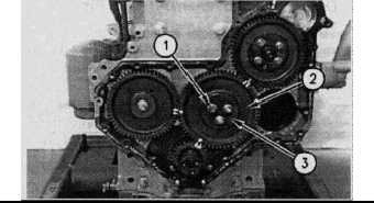
Illustration 141
8.
Install idler gear (2) and retainer plate (3) on the engine.
NOTE:
Ensure that the timing marks on the camshaft
gear, the crankshaft gear, and the idler gear are
aligned.
9.
Install three bolts (1) on idler gear (2).
10.
Check the end play of idler gear (2). Idler gear (2) can
have end play of 0.15 ±0.05 mm (.006 ±.002 inch).
11.
Check the backlash between the camshaft gear and
idler gear (2). The gears must have a minimum
backlash of 0.08 mm (.003 inch).
End By:
a.
Install the front cover. Refer to Disassembly and
Assembly, "Front Cover - Install".
7-57