
TM 5-3895-379-23
PROPEL CONTROL LEVER ASSEMBLY MAINTENANCE - CONTINUED
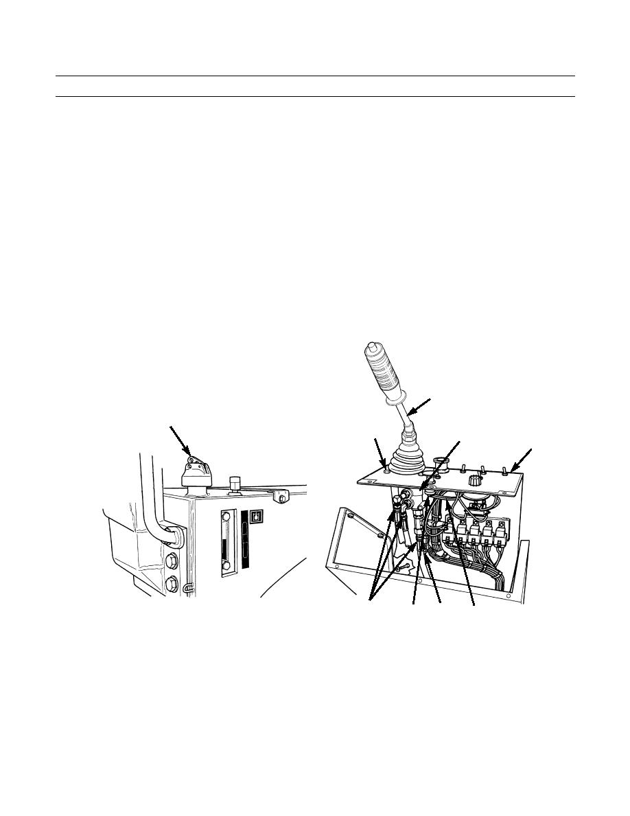
0113 00
REMOVAL - CONTINUED
3.
Loosen hydraulic oil tank fill cap (6) to release hydraulic pressure.
NOTE
Tag and mark all lines and wires to ensure correct installation.
Cap and plug all lines and fittings to prevent any contaminants from entering the system.
Use container to catch any oil that may drain from system. Dispose of oil IAW local policy and ordi-
nances. Ensure all spills are cleaned up.
4.
Remove four hose assemblies (7) from propel control valve (8).
5.
Disconnect electrical connector (10).
6.
Remove two wires (11) from backup alarm switch (12).
7.
Remove four bolts (13) and nuts (14) from plate assembly (5).
8.
Remove propel control valve (8) and lever assembly (9) as a unit from plate assembly (5).
9
6
13,14
8
5
7
10
12
11
401-2054
0113 00-3

