
TM 5-3895-379-23
TROUBLESHOOTING PROCEDURES - CONTINUED
0006 00
Table 6. Vibratory System Troubleshooting Procedures - Continued.
MALFUNCTION
TEST OR INSPECTION
CORRECTIVE ACTION
Remove all jewelry such as rings, dog tags and bracelets. If jewelry
contacts electrical connection a direct short may occur resulting in
injury or death, and damage to equipment.
Ensure that parking brake is engaged and propel control lever is in
neutral position before turning engine start switch to ON position. If
roller accidently starts or rolls, injury or death may occur.
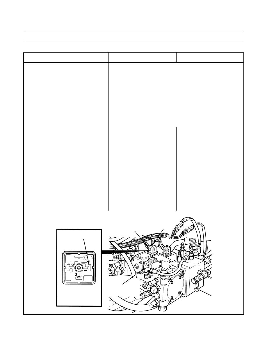
9.
Vibration Does Not Occur While
1. Check power to vibratory control. 1. If 24 to 28 Vdc are measured at
Amplitude Select Switch Is Set To
Open left-side door assembly (TM
terminal 1 (wire C925-GN), turn
High Pitch.
5-3895-379-10). Loosen screw
engine start switch and battery
and disconnect connector from
disconnect switch to OFF position
high amplitude solenoid. Turn
(TM 5-3895-379-10). Connect
battery disconnect switch and
connector to high amplitude
engine start switch to ON position
solenoid and tighten screw. Go to
(TM
5-3895-379-10).
Set
Step 2.
vibration control switch to manual
(MAN) position and amplitude
select switch to HI position. Set
multimeter to measure Vdc. Touch
positive (+) probe of multimeter to
terminal 1 (wire C925-GN) and
negative (-) probe of multimeter to
good ground.
SCREW
CONNECTOR
TERMINAL 1
HIGH
AMPLITUDE
SOLENOID
401-230

