
TM 5-3895-379-23
TROUBLESHOOTING PROCEDURES - CONTINUED
0006 00
Table 2. Electrical Troubleshooting Procedures - Continued.
MALFUNCTION
TEST OR INSPECTION
CORRECTIVE ACTION
1.
Connect main relay connector to
at output terminal of main relay
Continued.
harness connector. Turn engine
(wire 112-PU), replace main relay
start switch to ON position (TM
5-3895-379-10). Touch positive
(+) probe of multimeter to output 2. If 24 to 28 Vdc are measured at
output terminal of main relay,
terminal of main relay (wire 112-
replace or repair wire 112-PU and
PU) and negative (-) probe of
connectors (WP 0108 00) to fuses.
multimeter to good ground.
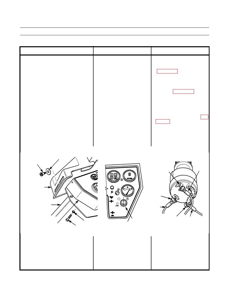
10. Check for power to engine start 1. If 24 to 28 Vdc are not present at
switch. Remove two shoulder
BAT terminal wire 105-BR), and
screws, washers and vandal guard
KEY START fuse is good, replace
from box assembly. Remove
or repair wiring and connectors to
three screws and washers and lift
KEY START fuse holder (WP
box assembly up from operator
station. Touch positive (+) probe
of multimeter to BAT terminal 2. If 24 to 28 Vdc are present at BAT
terminal, go to Step 11.
(wire 105-BR) of engine start
switch. Touch negative (-) probe
of multimeter to good ground.
SHOULDER
WASHER
SCREW
WIRE
START
307-OR
TERMINAL
VANDAL
BAT
GUARD
TERMINAL
OPERATOR
WIRE 105-BR
STATION
RELAY
WIRE
ENGINE
WASHER
TERMINAL
103-YL
START
INSTRUMENT
SCREW
SWITCH
PANEL
401-194
0006 00-51

