
TM 5-3895-379-23-2
0284
GENERAL TORQUE VALUES - Continued
Inch Series Four Bolt Flange Fittings Service Recommendations
CAUTION
1.
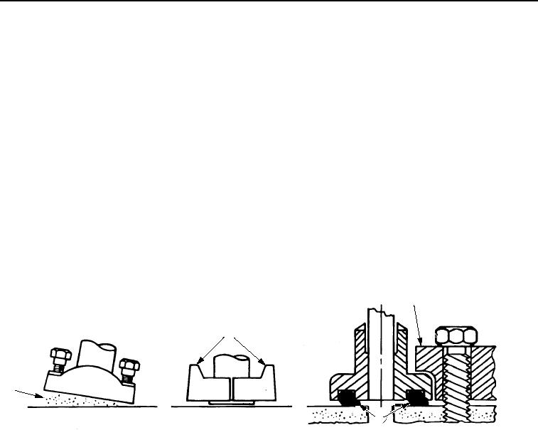
Clean sealing surfaces (Figure 22, Item 1). Inspect. Scratches cause leaks. Roughness causes seal wear.
Out-of-flat causes seal extrusion. If defects cannot be polished out, replace component.
2.
Install O-ring (Figure 22, Item and backup washer if required) into groove using clean oil to hold it in place.
Refer to LO 5-3805-294-13.
3.
Split flange: Loosely assemble split flange (Figure 22, Item 2) halves. Make sure split is centrally located and
perpendicular to port. Hand tighten cap screws to hold parts in place. Do not pinch O-ring (Figure 22, Item 3).
4.
Single piece flange (Figure 22, Item 4): Place hydraulic line in center of flange and install cap screws. Flange
must be centrally located on port. Hand tighten cap screws to hold flange in place. Do not pinch O-ring.
5.
After components are properly positioned and cap screws are hand tightened, tighten one cap screw, then
tighten the diagonally opposite cap screw. Tighten two remaining cap screws. Tighten all cap screws as
specified in the table.
4
2
1
3
M1337SWR
Figure 22.
Inch Series Four Bolt Flange Fitting.
03/15/2011Rel(1.8)root(torquewp)wpno(M00222)

