
TM 5-3895-379-23-2
0284
HOW TO USE THE TORQUE TABLE - Continued
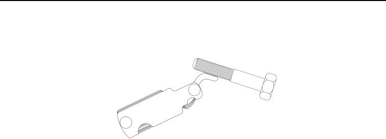
2. Measure thread pitch with thread pitch gage.
M1318SWR
Figure 2.
Thread Pitch Gage.
3. Under the heading, SIZE, look down the left-hand column until the diameter of the screw being installed is
found (there will usually be two lines beginning with the same size).
4. In the second column under SIZE, find the number of threads per inch that matches the number of threads
per inch counted in Step (2) (not required for metric screws).
5. To find the grade of screw, match the markings on the head with the correct picture of CAPSCREW HEAD
MARKINGS on the torque table.
6. Look down the column under the picture found in Step (5) until the torque limit (lb-ft or Nm) for the diameter
and threads per inch of the screw is found.
7. Use of adapters, crows foot, or other tools extending from the center of the torque wrench drive require that
a torque correction formula be used. Corrected torques are determined by the use of the following formula:
03/15/2011Rel(1.8)root(torquewp)wpno(M00222)

