
TM 5-3895-379-23-2
0277
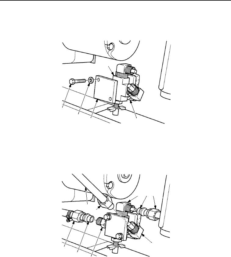
INSTALLATION - Continued
2.
Install tee (Figure 6, Item 1) and plate (Figure 6, Item 3) on bumper assembly (Figure 6, Item 2) with two screws
(Figure 6, Item 5) and washers (Figure 6, Item 4). Tighten screws to 84-132 lb-in. (9-15 Nm).
1
5
4
3
2
M0271SWR
Figure 6. Drain Cock and Tee Installation.
3.
Install two water lines (Figure 7, Items 1 and 4) on elbows (Figure 7, Items 3 and 6) with two nuts
(Figure 7, Items 2 and 5).
4.
Position water line (Figure 7, Item 8) on adapter (Figure 7, Item 7) and tighten nut (Figure 7, Item 9).
3
4
5
1
2
6
9
8
7
M0272SWR
Figure 7. Drain Cock and Tee Installation.
03/15/2011Rel(1.8)root(maintwp)wpno(M00215)

