
TM 5-3895-379-23-2
0224
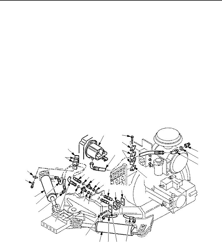
INSTALLATION
1.
Connect hose assembly (Figure 3, Item 2). Install elbow (Figure 3, Item 8) and new gasket (Figure 3, Item 7)
to hydraulic side of fuel/hydraulic oil tank (Figure 3, Item 6).
2.
Install two screws (Figure 3, Item 5), bracket (Figure 3, Item 4), two clamps (Figure 3, Item 3), and plate
(Figure 3, Item 9) to hose assembly (Figure 3, Item 2).
3.
Connect hose assemblies (Figure 3, Items 10 and 12) to hydraulic steering cylinder (Figure 3, Item 13).
4.
Install bolt (Figure 3, Item 14), cover (Figure 3, Item 11), two clamps (Figure 3, Item 24), and plate
(Figure 3, Item 25) to hose assemblies (Figure 3, Items 10 and 12).
5.
Install two nuts (Figure 3, Item 16), tees (Figure 3, Item 17), four new O-rings (Figure 3, Item 15), and hose
assemblies (Figure 3, Items 10 and 12) to frame.
6.
Connect hose assemblies (Figure 3, Items 18 and 19) to two tees (Figure 3, Item 17).
7.
Connect hose assemblies (Figure 3, Items 18 and 19) to hydraulic steering cylinder (Figure 3, Item 13).
8.
Install screw (Figure 3, Item 20), retainer (Figure 3, Item 21), two clamps (Figure 3, Item 22), and plate
(Figure 3, Item 23) to hose assemblies (Figure 3, Items 18 and 19).
9.
Connect hose assembly (Figure 3, Item 2) to steering pump (Figure 3, Item 1).
1
5
4
23
3
6
2
22
7
8
21
19
15 17
9
20
16
15
10
24 25
13
15
17
16
18
15
19
18
14
13
12
11
10
M1219SWR
Figure 3. Steering Hoses, Lines, and Fittings Installation.
03/15/2011Rel(1.8)root(maintwp)wpno(M00162)

