
TM 5-3895-379-23-2
0224
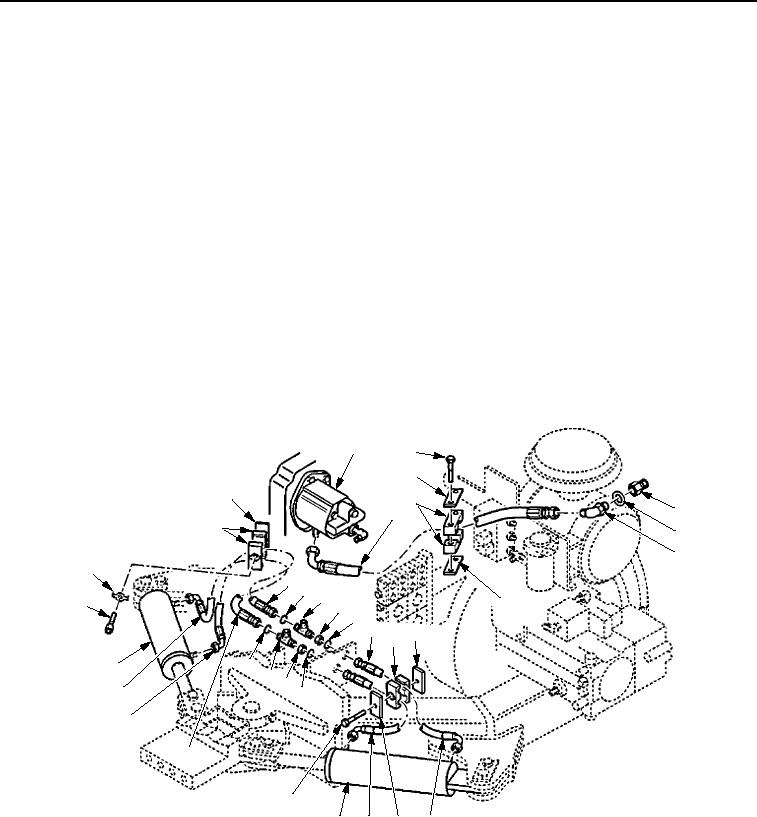
REMOVAL - Continued
9.
Disconnect hose assembly (Figure 2, Item 2) from steering pump (Figure 2, Item 1).
10.
Remove screw (Figure 2, Item 20), retainer (Figure 2, Item 21), two clamps (Figure 2, Item 22), and plate
(Figure 2, Item 23) from hose assemblies (Figure 2, Items 18 and 19).
11.
Disconnect hose assemblies (Figure 2, Items 18 and 19) from hydraulic steering cylinder (Figure 2, Item 13).
12.
Disconnect hose assemblies (Figure 2, Items 18 and 19) from two tee fittings (Figure 2, Item 17).
13.
Remove two nuts (Figure 2, Item 16), tee fittings (Figure 2, Item 17), four O-rings (Figure 2, Item 15), and two
hose assemblies (Figure 2, Items 10 and 12) from frame. Discard O-rings.
14.
Remove bolt (Figure 2, Item 14), cover (Figure 2, Item 11), two clamps (Figure 2, Item 24), and plate
(Figure 2, Item 25) from hose assemblies (Figure 2, Items 10 and 12).
15.
Disconnect hose assemblies (Figure 2, Items 10 and 12) from hydraulic steering cylinder (Figure 2, Item 13).
16.
Remove two screws (Figure 2, Item 5), bracket (Figure 2, Item 4), two clamps (Figure 2, Item 3), and plate
(Figure 2, Item 9) from hose assembly (Figure 2, Item 2).
17.
Disconnect hose assembly (Figure 2, Item 2) and remove elbow (Figure 2, Item 8) and gasket
(Figure 2, Item 7) from hydraulic side of fuel/hydraulic tank (Figure 2, Item 6). Discard gasket.
1
5
4
23
3
6
2
22
7
8
21
19
15 17
9
20
16
15
10
24 25
13
15
17
16
18
15
19
18
14
13
12
11
10
M0695SWR
Figure 2. Steering Hoses, Lines, and Fittings Removal.
END OF TASK
03/15/2011Rel(1.8)root(maintwp)wpno(M00162)

