
TM 5-3895-379-23-2
0222
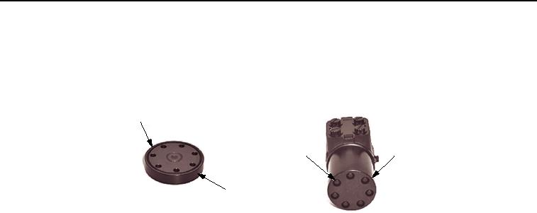
ASSEMBLY - Continued
18.
Install seal (Figure 16, Item 1) in end cap (Figure 16, Item 3).
19.
Install cap (Figure 16, Item 3) with seven screws (Figure 16, Item 2) on steering control unit (SCU). Tighten
capscrews in sequence shown to 150 lb-in. (17 Nm) ⇀ 275 lb-in. (31 Nm).
1
2
3
3
M1092SWR
Figure 16. Steering Control Unit (SCU) Assembly.
20.
Install steering control unit (SCU). Refer to INSTALLATION in this work package.
END OF TASK
INSTALLATION
1.
Spline the steering control unit (SCU) (Figure 17, Item 6) in steering column (Figure 17, Item 3).
2.
Install four new lockwashers (Figure 17, Item 5) and bolts (Figure 17, Item 4) to fasten steering control unit
(Figure 17, Item 6) and steering column (Figure 17, Item 3) and console (Figure 18, Item 3). Tighten bolts to
10-25 lb-ft (14-34 Nm).
NOTE
Remove all caps and plugs from hoses prior to installation.
Remove tags from hoses after hoses are connected correctly.
3.
Install new O-rings (Figure 17, Item 2) into four hoses (Figure 17, Item 1).
4.
Connect four hoses (Figure 17, Item 1) to steering control unit (Figure 17, Item 6).
03/15/2011Rel(1.8)root(maintwp)wpno(M00160)

