
TM 5-3895-379-23-1
0207
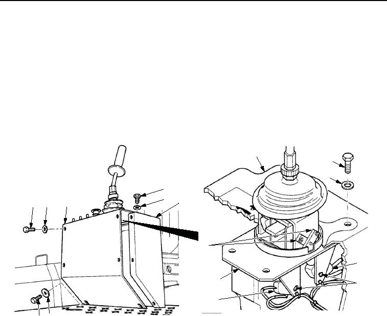
ADJUSTMENT - Continued
8.
Lift panel assembly (Figure 2, Item 3) and pull away from operator station (Figure 2, Item 4).
9.
Remove four screws (Figure 2, Item 5), washers (Figure 2, Item 6), and propulsion control valve assembly
(Figure 2, Item 9) from panel assembly (Figure 2, Item 3).
10.
Loosen two screws (Figure 2, Item 8) and move two engagement switches (Figure 2, Item 7) up until cams
(Figure 2, Item 10) engage switches (Figure 2, Item 8). Tighten screws.
11.
Install propulsion control valve assembly (Figure 2, Item 9) on panel assembly (Figure 2, Item 3) with four
washers (Figure 2, Item 6) and screws (Figure 2, Item 5).
12.
Install panel assembly (Figure 2, Item 3) on operator station (Figure 2, Item 4) with two washers
(Figure 2, Item 11), seven washers (Figure 2, Item 2), and nine screws (Figure 2, Item 1).
3
5
6
1
2
4
3
2
1
10
7
9
8
7
1 11
M0377SWR
Figure 2. Engagement Stops Adjustment.
13.
Repeat Steps (2) through (5).
03/15/2011Rel(1.8)root(maintwp)wpno(M00145)

