
TM 5-3895-379-23-1
0184
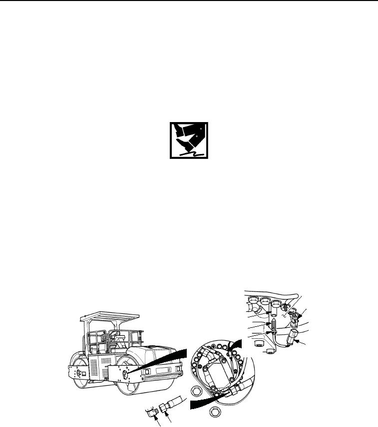
REMOVAL
NOTE
Right and left-front vibration sensors are maintained the same way. Right-front sensor is
shown.
Vibration sensors are located on left-side of rear drum and right-side of front drum.
1.
Disconnect connector (Figure 1, Item 2) from vibratory sensor connector (Figure 1, Item 3).
WARNING
Oil is very slippery. Immediately wipe up any spills. Failure to follow this warning may cause
injury.
NOTE
Use drain pan to catch any hydraulic oil that may drain from hose assembly. Dispose of oil
IAW local policy and ordinances.
2.
Place drain pan with 2 qt (1.9 Liters) minimum capacity under hose assembly (Figure 1, Item 4).
3.
Disconnect hose assembly (Figure 1, Item 4) from elbow (Figure 1, Item 5) and allow hydraulic fluid to drain
into drain pan.
4.
Loosen nut (Figure 1, Item 6) and remove vibration sensor (Figure 1, Item 7) and spacer (Figure 1, Item 8)
from plate (Figure 1, Item 1).
1
2
8
7
6
3
4
5
M0957SWR
Figure 1. Vibration Sensor Removal.
END OF TASK
03/15/2011Rel(1.8)root(maintwp)wpno(M00122)

