
TM 5-3895-379-23-1
0176
INSTALLATION - Continued
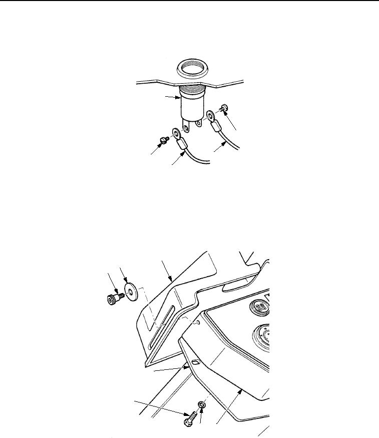
4.
Install two wires (Figure 6, Item 3) on lamp assembly (Figure 6, Item 1) with screws (Figure 6, Item 2).
1
2
3
2
3
M1104SWR
Figure 6.
Alternator Light Installation.
5.
Install instrument box assembly (Figure 7, Item 7) on operator station (Figure 7, Item 4) with three washers
(Figure 7, Item 5) and screws (Figure 7, Item 6).
6.
Install vandal guard (Figure 7, Item 3) on instrument box assembly (Figure 7, Item 7) with two washers
(Figure 7, Item 2) and shoulder screws (Figure 7, Item 1).
3
2
1
7
6
5
4
M1103SWR
Figure 7.
Alternator Light Installation.
03/15/2011Rel(1.8)root(maintwp)wpno(M00114)

