
TM 5-3895-379-23-1
0159
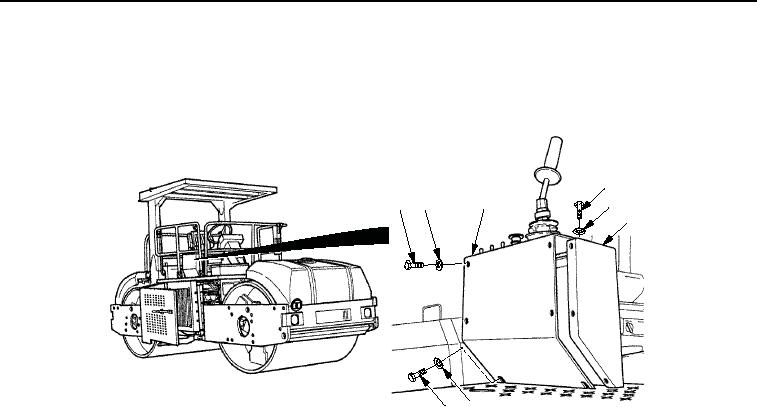
INSTALLATION - Continued
3.
Install panel assembly (Figure 6, Item 3) on operator station (Figure 6, Item 4) with two washers
(Figure 6, Item 5), seven washers (Figure 6, Item 2), and nine screws (Figure 6, Item 1).
1
3
1
2
2
4
5
1
M0872SWR
Figure 6.
Vibration Control Switch Installation.
END OF TASK
FOLLOW-ON MAINTENANCE
1.
Close right-side door assembly. (TM 5-3895-379-10)
2.
Remove chocks. (TM 5-3895-379-10)
END OF TASK
END OF WORK PACKAGE
0159-5/6 blank
03/15/2011Rel(1.8)root(maintwp)wpno(M00097)

