
TM 5-3895-379-23-1
0086
INSTALLATION
WARNING
Use caution when handling heavy parts. Provide adequate support and use assistance during
procedure. Ensure that any lifting device used is in good condition and of suitable load
capacity. Keep clear of heavy parts supported only by lifting device. Failure to follow this
warning may cause injury or death.
NOTE
If flywheel ring rear teeth are damaged, replace flywheel assembly.
Weight of flywheel assembly is 120 lb (54 kg).
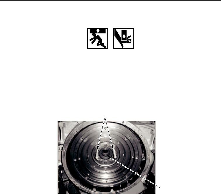
1.
Install two guide bolts (Figure 4, Item 1) to crankshaft (Figure 4, Item 2).
1
2
M1122SWR
Figure 4. Flywheel Assembly Installation.
2.
Install link bracket (Figure 5, Item 3) to flywheel assembly (Figure 5, Item 2).
3.
Attach lifting device to link bracket (Figure 5, Item 3) and flywheel assembly (Figure 5, Item 2).
4.
With assistance, lift flywheel assembly (Figure 5, Item 2) into flywheel housing (Figure 5, Item 1).
5.
Install six washers (Figure 5, Item 5) and bolts (Figure 5, Item 4) into flywheel assembly (Figure 5, Item 2) and
crankshaft (Figure 5, Item 6). Tighten bolts to 77 lb-ft (104 Nm).
6.
Remove lifting device and link bracket (Figure 5, Item 3) from flywheel assembly (Figure 5, Item 2).
7.
Remove guide bolts (Figure 5, Item 7) from flywheel assembly (Figure 5, Item 2).
03/15/2011Rel(1.8)root(maintwp)wpno(M00025)

