
DETROIT DIESEL 53
Shop Notes 2.0
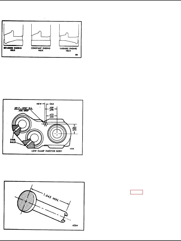
FUEL INJECTOR PLUNGERS
The fuel output and the operating characteristics of an
injector are, to a great extent, determined by the type of
plunger used. Three types of plungers are illustrated in
Fig. 4. The beginning of the injection period is controlled
by the upper helix angle. The lower helix angle retards or
advances the end of the injection period. Therefore, it is
imperative that the correct plunger is installed whenever
an injector is overhauled. If injectors with different type
plungers (and spray tips) are mixed in an engine, erratic
operation will result and may cause serious damage to the
engine or to the equipment which it powers.
Fig. 4. Types of Injector Plungers
Injector plungers cannot be reworked to change the output
or operating characteristics. Grinding will destroy the
hardened case and result in chipping at the helices and
seizure or scoring of the plunger.
REPLACING INJECTOR FOLLOWER SPRING
When replacing the injector follower spring (.120 "
diameter wire) in a low clamp body injector built prior to
June, 1965 with a new injector follower spring (.142 "
diameter wire), it will be necessary to relocate the timing
pin holes as illustrated in Fig..5, or grind .022 " from the
side of the injector timing gage shank, to permit continued
use of the injector timing gage.
Fig. 5. Relocating Timing Pin Hole in Injector Body
REFINISHING FACE OF INJECTOR FOLLOWER
When refinishing the face of an injector follower, it is
extremely important that the distance between the
injector face and the plunger slot is not less than the
1.645" minimum shown in Fig. 6.
If the distance between the injector face and the plunger
slot is less than 1.645 ", the height of the follower in
relation to the injector body will be altered and proper
injector timing cannot be realized.
NOTE: To ensure a sufficiently
hardened surface for rocker arm
contact, do not remove more than .010''
Fig. 6. Injector Follower
of metal from the injector follower head.
Page 4

