
1.7.4 Idler Gear
DETROIT DIESEL 53
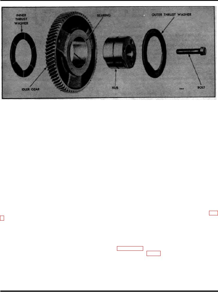
Figure 3. Idler Gear Details and Relative Location of Parts
the cylinder block. Then remove the idler gear hub and the idler gear inner thrust washer as an assembly.
Inspection
Wash the idler gear and bearing assembly, hub and thrust washers thoroughly in clean fuel oil and dry them
with compressed air. Examine the gear teeth and bearing for scoring, pitting and wear. If the gear teeth are
worn or the bearing is scored, pitted or worn excessively, replace the gear and bearing assembly or install a
new bearing in the gear. Examine the outside diameter of the idler gear hub and thrust washers; if scored or
worn excessively, replace them.
An idler gear bearing with two oil grooves has been incorporated in the idler gear and bearing assemblies
beginning with engine serial number 3D- 6773,
When a new bearing is installed in the idler gear, it must not protrude beyond the gear face on either side.
Install Idler Gear and Bearing Assembly
1. Place the inner thrust washer on the forward end of the idler gear hub with the flat in the inner diameter of
the thrust washer over the flat on the end of the gear hub and with the oil gro0yes in the thrust washer facing
the idler gear.
2. Place the small protruding end of the idler gear hub
through the end plate and into the counterbore in the cylinder block.
3. Insert two 3/8 "-16 bolts through the idler gear hub and thread them into the cylinder block, as shown in Fig.
1, to be sure the bolt holes will be in alignment when the flywheel housing is installed.
4. Insert the 3/8 "-16xl-3/4 " special bolt through the center of the idler gear hub and thread it into the cylinder
block. Tighten the bolt to 40-45 lb-ft torque. Then remove the two 3/8 "-16 bolts previously installed for
alignment of the gear hub.
5. Lubricate the idler gear hub and idler gear bearings liberally with clean engine oil.
6. Position the crankshaft gear and the camshaft gear or balance shaft gear so that their timing marks will
align with those on the idler gear. Refer to Figs. I and 2 in Section 1.7.1.
7. With these timing marks in alignment, install the idler gear as shown in Fig. 2.
8. Apply a thin film of cup grease to the inner face (face with the oil grooves) of the outer idler gear thrust
washer. Then place the thrust washer over the end of the idler gear hub with the oil grooves in the side of the
thrust washer facing the idler gear and the flat in the inner diameter of the thrust washer over the flat on the end
of the idler gear hub.
9. Check the backlash between the mating gears. The backlash should be .003 " to .005 " between new gears
and should not exceed .007 " between used gears.
Page 2

