
DETROIT DIESEL
Engine Tune-Up
10. When all of the injector rack control levers are
lever in the run position and press down on the
adjusted. recheck their settings. With the control tube
injector rack with a screw driver or finger tip and note
the "rotating" movement of the injector control rack
lever in the full-fuel position, check each control rack
as in Step 5. All of the control racks must have the
(Fig 4). Hold the stop lever in the run position and,
Same "spring" condition with the control tube lever in
using a screw driver. press downward on the injector
the full-fuel position.
control rack. The rack should tilt downward (Fig. 5)
and when the pressure of the screw driver is released,
11. Insert the clevis pin in the fuel rods and the
the control rack should "spring" bath upward. If the
injector control tube levers.
rack does not return to its original position, it is too
loose. To correct this condition, back off the outer
adjusting screw slightly and tighten the inner adjusting
12. Use new gaskets and install the valve rocker covers.
screw. The setting is too tight if, when moving the stop
lever from the stop to the run position, the injector
rack becomes tight before the governor stop lever
Adjust Maximum No-load Speed
reaches the end of its travel. This will result in a step-
up in effort required to move the stop lever to the run
position and a deflection in the fuel rod (fuel rod
All governors are properly adjusted before leaving the
deflection can be seen at the bend). If the rack is
factory. However, if the governor has been recondi-
found to be too tight, back off the inner adjusting
tioned or replaced, and to ensure the engine speed will
screw slightly and tighten the outer adjusting screw.
not exceed the recommended no-load speed as given
on the engine option plate, the maximum no-load
6. Remove the clevis pin from the fuel rod and the left
speed may be set as follows:
bank injector control tube lever.
Start the engine and after it reaches normal operating
7. Insert the clevis pin in the fuel rod and the right
temperature, determine the maximum no-load speed
cylinder bank injector control tube lever and position
of the engine with an accurate tachometer. Then stop
the No. 3R injector rack control lever as previously
the engine and make the following adjustments, if
outlined in Step 4 for the No. 3L control lever.
required.
8. Insert the clevis pin in the fuel rod and the left bank
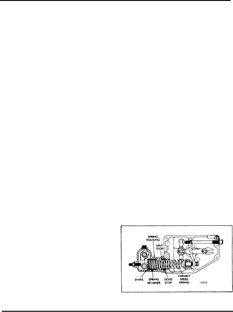
1. Refer to Fig. 9 and disconnect the booster spring
injector control tube lever. Repeat the check on the 3L
and the stop lever retracting spring.
and 3R injector rack control levers as outlined in
Step 5. Check for and eliminate any deflection which
2. Remove the variable speed spring housing and the
may occur at the bend in the fuel rod where it enters
spring retainer, located inside of the housing, from the
the cylinder head.
governor housing.
9. To adjust the remaining injector rack control levers,
3. Refer to Table 1 and determine the stops or shims
remove the clevis pin from the fuel rods and the
required for the desired full-load speed. A split stop
injector control tube levers, hold the injector control
can only be used with a solid stop (Fig. 6).
racks in the full-fuel position by means of the lever on
the end of the control tube and proceed as follows:
4. Install the variable speed spring retainer and
housing and tighten the two bolts.
a. Turn down the inner adjusting screw of the
injector rack control lever until the screw bottoms
(injector control rack in the full-fuel position).
b. Turn down the outer adjusting screw of the
injector rack control lever until it bottoms on the
injector control tube.
c. While still holding the control tube lever in the
full-fuel position, adjust the inner and outer
adjusting screws to obtain the same condition as
outlined in Step 5. Tighten the screws.
CAUTION: Once the No. 3L and No. 3R
injector rack control levers are adjusted, do not
Fig. 6 - Location of Shims and Stops
try to alter their settings. All adjustments are
made on the remaining control racks.
Page 100

