
TM 5-3895-346-14
ENGINE OVERHAUL
LUBRICATION SYSTEM
The blower bearings are pressure lubricated by oil from drilled passages in the cylinder block which connect
matching passages in the blower end plates which, in turn, lead to the bearings. On current engines, lubricating
oil is supplied directly to the front and rear right bank camshaft end bearings and supplies oil to the blower
bearings. On former engines, the blower bearings received lubrication indirectly via the right rear camshaft end
bearing only. Excess oil returns to the crankcase via drain holes in the blower end plates which lead to
corresponding drain holes in the cylinder block.
One tapped oil pressure take-off hole is provided in the lower engine front cover on some in-line engines. In
addition, tapped oil holes in the cylinder block, on the side opposite the blower, are also provided with three
holes in the four-cylinder block.
Lubricating System Maintenance
Use the proper viscosity grade and type of heavy-duty oil as outlined in the Lubricating Oil Specifications.
Change the oil and replace the oil filter elements at the periods recommended by the oil supplier (based on his
analysis of the drained engine oil) to ensure trouble-free lubrication and longer engine life.
The oil level should never be allowed to drop below the low mark on the dip-stick. Overfilling the crankcase
may contribute to abnormal oil consumption, high oil temperatures, and also result in oil leaking past the
crankshaft rear oil seal.
To obtain the true oil level, the engine should be stopped and sufficient time (approximately twenty minutes)
allowed for the oil to drain back from the various parts of the engine. If more oil is required, add only enough to
bring it to the proper level on the dipstick.
Cleaning Lubrication System
Thorough flushing of the lubrication system is required at times. Should the engine lubrication system become
contaminated by ethylene glycol anti-freeze solution or other soluble material, refer to Cooling System for the
recommended cleaning procedure.
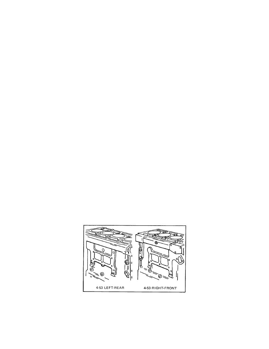
OIL PRESSURE TAKE-OFF LOCATIONS
The cylinder block illustrations in Fig. 2 show the main oil gallery pressure locations that are available for
supplying oil under pressure to oil gages, Jacobs engine brake, or other accessories.
Figure 2. Oil Pressure Take-Off Locations
309

