
TM 5-3895-346-14
BLOWER DRIVE SUPPORT
ENGINE OVERHAUL
BLOWER DRIVE GEAR AND SUPPORT ASSEMBLY
The blower drive gear is driven by the camshaft gear (4-53 engine). The gear is keyed and pressed on a shaft
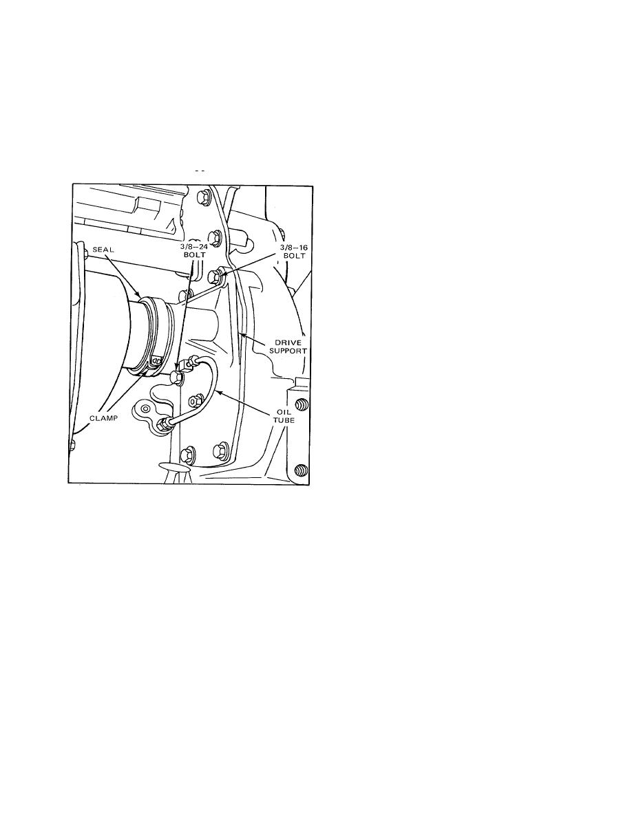
which is supported in the blower drive support. This support, on a 4-53 engine, is attached to the rear end plate
on the blower side of the engine (Fig. 1).
Remove and Install Blower Drive Shaft
1. Remove the air inlet housing from the blower (refer to Air Shutdown Housing).
2. Refer to Fig. 1 and loosen the blower drive seal clamp.
3. Slide the clamp and seal off of the blower drive support.
Figure 1. Blower Drive Support Mounting on 4-53 In-Line Engine
4. Remove the four blower-to-block bolts. Then carefully lift the blower away from the blower drive
support and the cylinder block so the serrations on the blower drive shaft are not damaged.
5. Withdraw the blower drive shaft from the blower drive support.
6. Install the shaft by reversing the removal procedure.
Remove Blower Drive Support
1. Remove the blower and the blower drive shaft as outlined above.
2. Disconnect the lubricating oil tube (Fig. 1) from the blower drive support.
3. Remove the blower drive support attaching bolts.
4. Tap the blower drive support to loosen it, then carefully withdraw the support from the rear end plate
so the blower drive gear teeth will not be damaged.
Disassemble Blower Drive Support
1. Remove the snapring and the thrust washer from the shaft.
2. If there are burrs on the edges of the snapring groove, remove them with a stone. Then withdraw the
gear and shaft from the support.
3. Support the blower drive gear in an arbor press (Fig. 2).
4. Place a short, 1-1/8-inch diameter brass rod on the end of the shaft and press the shaft out of the
gear.
Inspection
Thoroughly clean the parts with fuel oil and dry them with compressed air.
189

