
TM 5-3895-346-14
ENGINE OVERHAUL
VALVE OPERATING MECHANISM
2. Pull the cam follower out of the cylinder head.
3. Remove the fuel pipes from the injector and the fuel connectors.
CAUTION
Immediately after removing the fuel pipes, cover the injector fuel inlet and outlet
openings with shipping caps to prevent dirt or foreign material from entering.
4. Loosen the push rod locknut and unscrew the push rod from the rocker arm clevis.
5. Pull the push rod and spring assembly from the bottom of the cylinder head.
6. Remove the push rod locknut, spring, and spring seats from the push rod.
NOTE
If the cylinder head is to be replaced, remove the spring retainers and install them
in the new head.
Inspection
Proper inspection and service of the cam follower is very necessary to obtain continued efficient engine
performance. When any appreciable change in injector timing or exhaust valve clearance occurs during engine
operation, remove the cam followers and their related parts and inspect them for excessive wear. This change
in injector timing or valve clearance can usually be detected by excessive noise at idle speed.
CAUTION
Wash the cam followers with lubricating oil or Cindol 1705 and wipe dry. DO NOT
USE FUEL OIL. Fuel oil working its way in between the cam roller bushing and
pin may cause scoring on initial startup of the engine since fuel oil does not
provide adequate lubrication.
The push rods, springs, and spring seats may be washed with clean fuel oil and dried with compressed air.
Examine the cam follower rollers for scoring, pitting, or flat spots. The rollers must turn freely on their pins.
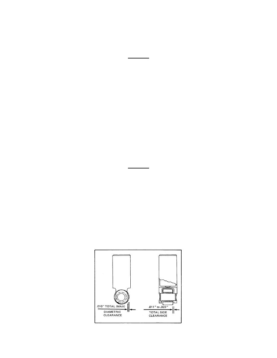
Measure the total diametric clearance and side clearance. Install a new roller and pin if the clearances exceed
those specified in Fig. 4. Cam followers stamped with the letter S on the pin, roller, and follower body are
equipped with an oversized pin and roller. The same clearances apply to either a standard or oversized cam
follower assembly.
Examine the camshaft lobes for scoring, pitting, or flat spots. Replace the camshaft, if necessary.
Figure 4. Cam Roller Clearances
84

