
Section VII. POWER TAKEOFF CLUTCH ASSEMBLY
4-10. Clutch Assembly Adjustment
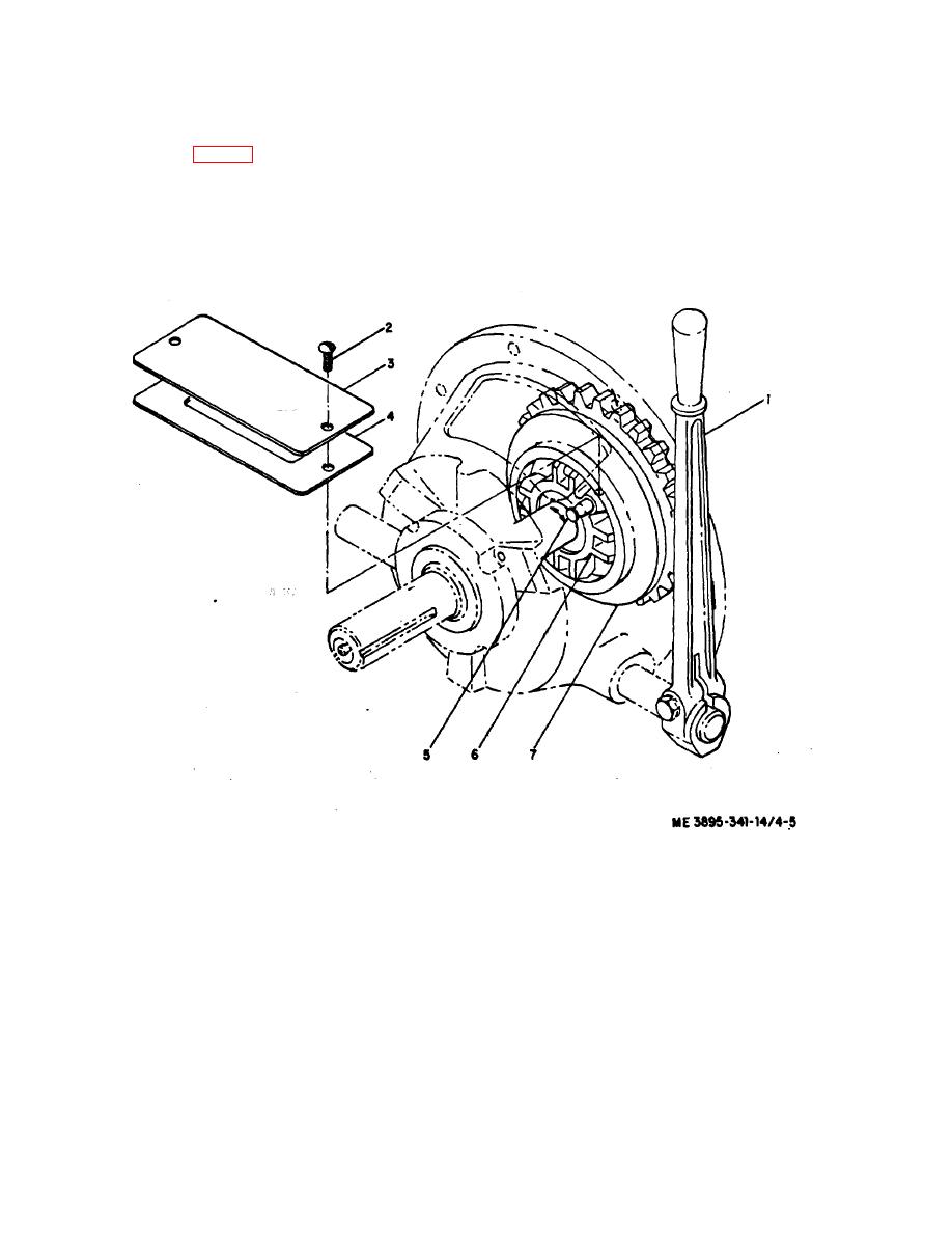
direction to tighten. Allow pin to reengage itself in one of
the holes in the floating plate (7).
d. Engage lever (1) to check clutch pressure. When a
2-3).
slight pressure is felt at engagement with a snap into
b. Remove screws (2), plate (3) and gasket (4).
place, the clutch is adjusted properly. Disengage lever.
c. Turn clutch until spring-loaded pin (5) is in full view.
e. Replace gasket (4) and plate (3) with screws (2).
Pull out pin and turn adjusting yoke (6) in clockwise
1
Lever, Operating
2
Screw, Machine
3
Plate, Model
4
Gasket
5
Pin
6
Yoke, Adjusting
7
Plate, Foating
Figure 4-5. Clutch Adjustment.
4-9

